


By Nicholas Brown.
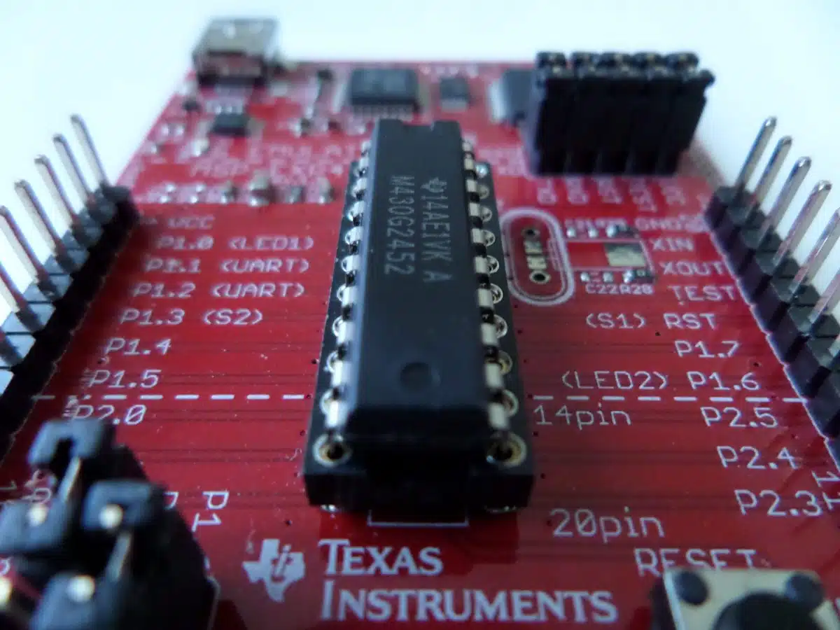
For this MSP430 PWM example, we will write a very simple program for the TI Launchpad MSP430G2553 development kit that generates a PWM signal at pin 1.2 with a duty cycle of 50%.
This model of Launchpad has been discontinued. However, there is a similar model available if you don’t already have this G2 model.
A Brief Introduction To PWM
PWM stands for pulse-width modulation, and the width of each pulse is actually the period that the power is on. The duty cycle is the percentage of the time that the power is on. This means that a duty cycle of 50% entails turning the power on for half the time, and then off for the other 50% of the time.
This happens many times per second, so you won’t be able to see exactly what’s happening without an oscilloscope. However, you can test it by checking the voltage of the pins as explained below, or connect a discrete LED to pin 1.2. You can check the voltage with a multimeter, or get a closer look at the PWM waveform using an oscilloscope.
A discrete LED (this is the smallest type of LED, often used for keyboard backlights, hard drive access lights, etc) is required, as microcontrollers are not intended to supply large currents. The LED should turn on normally, but be roughly 50% of its maximum brightness.
PWM is advanced, but simple, and it opens a window of opportunity for more efficient machines. All you need is an MCU with a timer and GPIO knowledge. You could also use transistors (in the form of a darlington pair, a darlington transistor, or a MOSFET) to control a bright LED to scale this up for room or other bright lighting.
If you aren’t familiar with GPIO, which is the cornerstone of PWM, you can learn how it works here. For a more comprehensive explanation of PWM, read Kompulsa’s introduction to PWM.
The code below generates a square wave.
#include <msp430g2553.h>


int main(void) {

    WDTCTL = WDTPW + WDTHOLD; //Disable the Watchdog timer for our convenience.

    P1DIR |= BIT2; //Set pin 1.2 to the output direction.

    P1SEL |= BIT2; //Select pin 1.2 as our PWM output.

    TA0CCR0 = 1000; //Set the period in the Timer A0 Capture/Compare 0 register to 1000 us.

    TA0CCTL1 = OUTMOD_7;

    TA0CCR1 = 500; //The period in microseconds that the power is ON. It's half the time, which translates to a 50% duty cycle.
    TA0CTL = TASSEL_2 + MC_1; //TASSEL_2 selects SMCLK as the clock source, and MC_1 tells it to count up to the value in TA0CCR0.

    __bis_SR_register(LPM0_bits); //Switch to low power mode 0.

}
If you divide the value we assigned to TA0CCR1 by the one we assigned to TA0CCR0, you’ll see that we chose a 50% PWM duty cycle for this example. If you wanted a PWM duty cycle of 25%, you would simply write a value of 250 to TA0CCR1.
You can confirm that it is working by using a multimeter or voltmeter to check the voltage of the VCC pin on the development kit as well as the voltage of pin 1.2, then divide the voltage of pin 1.2 by the VCC voltage. Your result should be 0.5, which denotes a duty cycle of 50%.
I used that code to make a dimmable PWM LED lamp using a simple resistor and transistor, as shown below (it’s also very energy-efficient). A capacitor can also be used to smooth out the waveform.
Next: Sample Code: Build A PWM LED Dimmer For $12 (Using An MSP430)
Glossary
TA0CCR0: Timer A0, Capture/Compare Register 0.
TA0CCR1: Timer A0, Capture/Compare Register 1.
TA0CCTL1: Timer A0, Capture/Compare Control Register 1.
TA0CTL: Timer A0 Control Register.
Further Reading: Reduce The MSP430’s Power Consumption.